Earth Notes: Low-Voltage Disconnect for 12V RE System (2007)
Updated 2022-12-02.In order to power my low-power laptop/server from my 12V solar PV Renewable Energy (RE) system shared with my 12V office lighting, I need a low-voltage disconnect (LVD) circuit to:
- Protect the battery against damagingly-deep discharge.
- Reserve plenty of power for lighting in the evening.
The laptop actually requires 20V @ 3.25A max, and therefore I need a small and efficient DC-to-DC converter. A car laptop power supply is ideal, and should also filter out nasty spikes, etc.
Other names for this type of battery protection include:
- Low Voltage Drop-out
- Low Voltage Cut-out
- Low Voltage Cut-off
- Low Voltage Disconnect
- Low Voltage Shutdown
MAX8212
This design uses a MAX8212 IC intended for battery monitoring, containing a precision voltage reference, and with very low current draw, that needs only two or three resistors to set up.
I use the MAX8212 output to directly drive a high-side p-channel power MOSFET to connect the power to the load (and disconnect when the battery is too low). Since this is either fully-on or fully-off, it dissipates almost no heat.
This also drives an opto-isolator and a LED indicator for visual and computer monitoring of the connect/disconnect state.
I use transient-suppressor diodes and a decent-sized capacitor to help absorb spikes (etc) from other equipment and the wiring runs, and our load should it have any significant inductive component, especially given the fast switching for load connect/disconnect.
This has to be able to handle a load of several amps peak (the peak laptop power-draw is ~70W which implies ~6A continuous). This has to handle a much higher start-up (inrush) current at turn-on.
This must use absolutely-minimal power when the battery is low, since any significant continued discharge may damage the battery (through "sulphation"/"sulfation"). This design draws microamps when it has disconnected the load.
When the load is connected this draws a few milliamps itself.
Hysteresis
This uses hysteresis to:
- Avoid oscillating at power-off when the battery voltage rises after load removal. Trial-and-error suggested that this had to be at least 500mV (0.5V), and 1V seems a lot more stable.
- Give the battery chance to get a good charge (ie recover) after a deep discharge.
I have the lower (disconnect) threshold set at about 12.15V and the upper threshold set at about 13.45V. The high threshold should generally ensure that the load is reconnected only when the battery is being charged in good sunlight. (In fact, spikes from other equipment can cause this to be exceeded long enough to trigger the LVD to reconnect the load briefly.)
Given how complicated the relationship of State-of-Charge (SOC) of the battery to voltage is, the threshold and hysteresis values are difficult to get right, especially as I want to interact well with the SHS-6 LVD for my lighting. However, it is clear that there is about 1V difference for a given SOC between the battery being charged and being discharged, so the hysteresis probably has more than this, ie over 1V, which is what I now have.
I have added a small 'smoother' to the voltage-divider network for the MAX8212 to reduce oscillation/instability, especially given the huge start-up current of the DC-DC converter load.
Revision 3: Working LVD
While not perfect, the LVD and 20V switchover parts seem to be reliable, and I feel confident to leave them on 24x7. I can monitor remotely when solar power is being supplied to the laptop, which adds to my comfort. 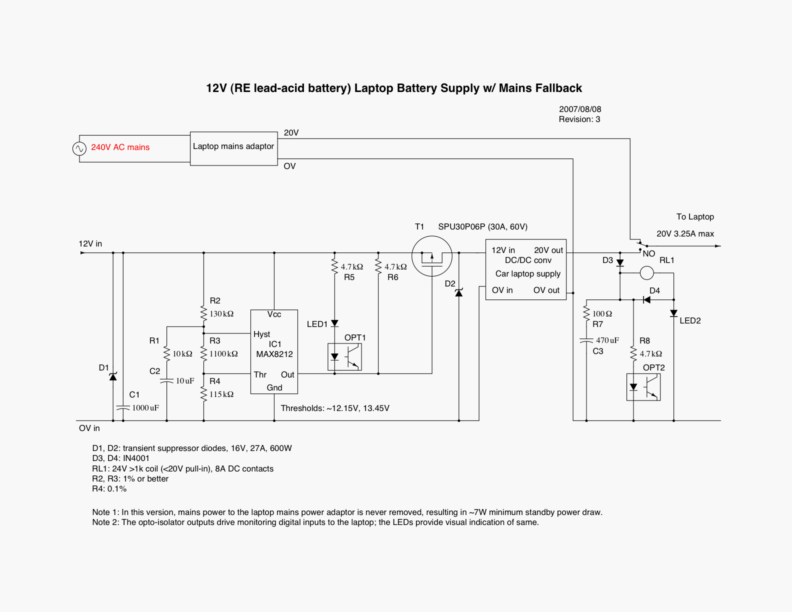
XCircuit .ps file.
The MAX8212 and the resistor network R2/R3/R4 sense the battery voltage, turning off power to the DC-DC converter when the voltage gets too low, ie when the battery is getting too discharged, and turning the power back on when the battery has recovered enough and the battery is being charged (the higher threshold voltage is higher than can be seen on a resting or discharging 12V lead-acid battery). The R1/C2 circuit attempts to make the sensing circuit less prone to spikes and to oscillation when starting to power a heavy load. The main disadvantage of this tweak is the possibility of triggering something like 'SCR latch-up' on the HYST pin; R1 is there to limit peak current flow and mitigate the latch-up issue.
D1 and D2 are there to absorb inductive and other spikes at the input and output and should always keep the voltages at IC1 (and T1) within absolute maximum ratings. C1 is also there to help absorb inductive spikes, and to help supply inrush/start-up current to the load. A larger value (or even a small ultracapacitor) might be a useful upgrade. The power MOSFET T1 is hugely overrated for the typical 2A to 6A at 12V it is expected to handle to help survive spikes etc. Because T1 should basically always be hard on or hard off it does not seem to need a heatsink and has never been even warm.
IC1's "OUT" is an open-drain pull-down, active when the battery voltage is OK, and so R6 (and R5/LED1/etc) pull it up relatively quickly to disconnect the load when OUT is inactive.
Basically the relay RL1 is arranged to switch laptop power to be from the DC-DC converter when the converter is running, in turn when the LVD has connected the converter to the 12V battery because the battery voltage and thus charge are high enough. The circuitry around the coil is the help avoid the relay switching too rapidly even if the 20V converter output is not stable for whatever reason (eg oscillation in the LVD). LED2 also drops the voltage available to the coil a little so that the coil's guaranteed pull-in at about 70% of its 24V nominal won't happen until the converter's output voltage is reasonably close to 20V, and thus good for the laptop.
Visual indication is provided by LED1 and LED2 of battery state and the DC-DC converter output actually being adequate to drive the laptop. The optoisolators OPT1 and OPT2 (with the transistor outputs connected to digital inputs on the k8055 USB I/O board) provide exactly the same information to the laptop so that it can monitor where its external power is coming from, since 'external' no longer simply means AC mains. Note that the current for the LEDs and optoisolators is almost 'free' in this design since we have to have for T1 gate pull-up and the RL1 coil anyway. (Possibly the series resistor R8 could be a little higher to reduce power wastage.)
All of this was built on a short piece of copper strip-board, with power connections being handled via terminal blocks and 2.1mm and 2.5mm DC power plugs and sockets, and a car cigarette socket from the LVD output for the DC-DC converter to plug into.
: Update/Simplification
As of ~2008-06-25 the laptop battery seems to have died. This means that the laptop would crash if there was even the slightest interruption in its power supply. Thus the relay-based switchover system was no longer viable. So I established with a digital voltmeter the open-circuit output voltage (both nominally 20V) of the laptop adapter (20.85V) and the converter (20.47V). I have taken the decision that the DC-DC converter is expendable if need be (and indeed I have a spare), so I have commoned the adaptor and converter -ve/0V outputs as before (and they run to the laptop -ve/0V power input), and connected the adapter +ve output via a P600A 6V silicon power rectifier to the +ve output of the converter and on to the laptop power +ve input. If the converter output is on (LVD output is on) then it will power the laptop since the mains adapter voltage after the ~0.7V rectifier drop is lower. (Note that a Schottky diode would not have a big enough voltage drop to make this scheme work.) But the moment the DC-DC converter output drops, eg because the off-grid battery voltage is low, then the laptop adapter should take over instantly without a gap, ensuring that the laptop does not crash. The upside is instant/silent switch-over and no mechanical relay to wear out. The two small downsides are:
- a slight risk to the DC-DC converter in having its output driven to 20V when its input is not powered,
- power loss in the rectifier when the system is on mains power, though that should be much less than 1W in practice.
I have verified that with this circuit power is not drawn from the adapter when the DC-DC converter has input power, ie the mains adapter drops back to its typical 2W 'idle' power draw.
As of 2008-07-21 this arrangement seems to be working without a hitch.
: High State-Of-Charge (SOC) Detector
As of 2007-09-04 I have constructed a high-SOC detector that feeds into the USB digital inputs that is independent of the LVD circuit. This means that the laptop can tell when the battery voltage (and charge) is high and and the battery is charging, so that (when the laptop is also being powered from the 12V battery) the laptop can use more power to run faster and do important but non-essential work such as disc checking and my AI computations. 
.ps XCircuit file. 
Note that this effectively an automatic dump load that does computational work rather than running a heating element (the CPU is the heater here!). If you are running something such as a wind turbine which cannot safely simply disconnect when the battery is full (unlike solar PV), then you should still have a normal dump load, but this can help make slightly more sophisticated use of some of the available extra energy if you make sure that the normal dump voltage (typically a little over 14V) is set higher than this monitor/detector comes on at.
The thresholds are set at 13V/13.5V. Much less hysteresis is needed than for the LVD since this does not directly cause an immediate huge battery drain, and any response to changes is mediated in software and may take up to several minutes, so damaging/fast oscillation is unlikely.
I do see induced noise from my WiFi router trigger this, plus what appear to be spikes from (for example) my small turbine, so this can be showing 'high voltage' then the main LVD stays off. The software only takes any notice of this signal when the LVD is on too.
: NiMH Battery Charger as Dump Load

As of 2010-07-17 I have bought a Maplin N42FK AA/AAA NiMH battery fast charger that can run in a car (at 12V) and that has a timer and -deltaV cutoffs, ie should be safe to leave completely unattended with cells in. It has a charge-state indicator which should help us know when the NiMH cells are full so that we can take them out and put them in out 'charged' box and rotate others in from out 'uncharged' set.
I have put this downstream of the LVD which was no longer being used for the laptop now that I am using the SheevaPlug for the Internet server. The idea is that when the off-grid SLA battery is full-ish (and charging) then excess energy will be diverted to charging any NiMH cells in the charger. (Also the server will ramp up its work/consumption at its own chosen voltage thresholds as additional 'dump load'.)
This means that when there is excess off-grid solar energy available this can use a little of it recharging NiMH cells semi-automatically. When there are no batteries/cells waiting to be charged then the server gets to use all the energy that it can. In any case this wastes less of what is available and 'free'!
I may want to increase the LVD lower threshold to make this more like a dump, but given that this is a fast charger rather than trickle, possibly the current threshold does allow us to really charge on demand providing that the off-grid system has plenty of energy to spare.
: Reuse
2018-07-12: right now I would like to add more dump load to the off-grid system to "use it, not lose it". Without enough suitable load it is difficult to get the most from the off-grid PV even in mid-summer.
At the same time I am contemplating significant behind-the-meter storage for the grid-tie system. Even if I can power loads via AC-coupled storage for most the the year, it's better to keep the load from the grid side entirely where possible to leave as much as possible for the grid.
This is a proxy for something I'm not allowed to do, which is feed energy into the grid from my off-grid system.
I don't like the fact that the SmartThings hub is consuming ~10W, ie 250Wh/d, from the grid year round.
The SmartThings hub power supply is apparently ~5V (at 2A), so it may be possible to leave its mains supply plugged in, but power the hub via the LVD via a USB supply when there is enough juice in the system. No intervention from the power management code on the RPi would be needed. This would take the load able to be transferred off-grid automatically from ~400Wh to ~650Wh. That would be ~10% of typical gross daily grid consumption.
(If the energy is available, running my laptop from the off-grid system could get the total up towards 1kWh/d, depending on what I'm doing. Running simulations is more CPU intensive than doomscrolling Twitter, usually.)
Possibly the lower (disconnect) threshold may need to be pushed up a little, to less aggressively discharge the off-grid battery. But looking at the 12V nominal numbers as seen by the RPi (BV), even when the battery is in a reasonable state, suggests that it may be OK. That's assuming that the low threshold is still ~12.15V.
2018/07/11T01:00:06Z AL 0 B1 12433 B2 -1 P 16350 BV 12140 ST OK D e A1P 0 B1T 24 UC 78
2018/07/11T01:10:06Z AL 0 B1 12433 B2 -1 P 16412 BV 12122 ST OK D e A1P 0 B1T 24 UC 78
2018/07/11T01:20:06Z AL 0 B1 12433 B2 -1 P 16375 BV 12084 ST OK D e A1P 0 B1T 24 UC 78
2018/07/11T01:30:06Z AL 0 B1 12397 B2 -1 P 16303 BV 12103 ST OK D e A1P 0 B1T 24 UC 71
For now, I have simply plugged the LVD box into a spare 12V socket from the off-grid system by my desk to keep an eye on whether it sees to go on and off at reasonable times. (Next day: behaviour is looking sensible...)
It seems that the SmartThings Hub may only be drawing ~1W while I am watching, but while trying as a trial to wire it directly 'permanently' off-grid, two (elderly) power supplies died, my Internet router died, and then my entire Internet Service Provider lost connectivity and phones due to something failing at Telehouse. So I'll just stop now before the entire National Grid takes a Friday afternoon lie-down.
At least that fright kicked off overdue Raspberry Pi 3 development/upgrade work!
: Reuse
2019-07-18: I have indeed been using this in conjunction with my NiMH fast charger for AA and AAA cells to set up a charge before I go out in the morning, knowing that good things should happen automatically before I come back, but not until the sun is out.
: Summer Redeployment for the MacBook?
I had to give up powering my MacBook Air off-grid because on the little car adaptor I was using (set to 15V) the cigar plug part melted. Those connectors really are not much good at sustained high loads if heat is not what you're after!
I note that I am already in April not soaking up all the energy that my expanded off-grid system has available, partly because the storage is ailing.
If I can't use it at the time, I lose it!
In principle I could re-use the LVD system to power my MacBook automatically when the sun is out, as I used to with the old laptop back in 2008! I don't leave the MacBook powered up the whole time, but it probably gets well over 10 hours' use per day's use during daylight, and thus probably 50--100Wh consumption per day. That could reasonably be added to off-grid consumption in summer.
The MacBook mains adaptors draw very little from the mains when not loaded with the Mac. Maybe 0.1W.
I'd have to beef up the LVD controller wiring for the heavier load, and cut into a working mains adaptor if I want to automate the switchover as before.
More simply, I could just power the MacBook via the LVD and adaptor manually as I have in the past, swapping Magsafe physical connections to go back on mains when needed. That leaves my Mac coasting on its battery for a while if I don't notice, rather than having the 12V adaptor scream from low voltage!
: MacBook and LVD Lash-up
I have today powered the MacBook via the car charger and LVD.
Here is a segment with the LVD dropping out after the first sample, then just as it comes back. The battery voltage is as seen at the solar controller:
2021/04/25T16:30:35Z AL 1394 B1 13285 B2 -1 P 32961 BV 12968 ST OK D E A1P 18602 B1T 14 UC 100 A1V 28232
2021/04/25T16:30:41Z AL 1469 B1 13279 B2 -1 P 15378 BV 13047 ST OK D E A1P 19583 B1T 14 UC 100 A1V 28232
2021/04/25T16:30:47Z AL 1472 B1 13285 B2 -1 P 15411 BV 13065 ST OK D E A1P 19614 B1T 14 UC 100 A1V 28232
2021/04/25T16:30:53Z AL 1469 B1 13294 B2 -1 P 16392 BV 13047 ST OK D E A1P 19478 B1T 14 UC 100 A1V 28232
...
2021/04/25T16:34:53Z AL 1568 B1 13486 B2 -1 P 28901 BV 12152 ST H D E A1P 21063 B1T 14 UC 100 A1V 28568
2021/04/25T16:35:00Z AL 1600 B1 13477 B2 -1 P 25270 BV 12135 ST H D E A1P 21229 B1T 14 UC 100 A1V 28565
The hysteresis may be enough to keep things sane, though cycles of under a minute seem possible, even under fairly light steady load (eg MacBook Air's battery full).
Powering the MBA off-grid during the day is likely key to shifting more than 300Wh/d away from the grid.
2021-04-26: LVD came on at ~09:15Z (there is quite a lot of cloud) and I have taken the MBA off-grid.
~09:35Z: heavy MBA workload and direct sun coming and going, is having the LVD drop out and come back a many times... So the MBA coasts for a while on batteries when the LVD drops. The lamp on the MagSafe connector can flicker a bit before that happens. I'm hoping that this cycling is not hurting anything!

: MacBook and LVD Wired In
Should I simply leave the LVD wired in permanently (well, until winter)? Partly I ask because finding a 10A 12V switch has been quite hard. Also because the cigar-lighter socket really is not good for this sustained load. Below the first four samples are with the LVD circuit disconnected. The next four are with it connected, but the load powered off. The extra load is difficult to detect: maybe 100mW? For outside winter this is probably entirely acceptable.
2021/04/27T05:31:43Z AL 148 B1 12549 B2 -1 P 2736 BV 12442 ST L - L A1P 1843 B1T 11 UC 44 A1V 23478
2021/04/27T05:31:50Z AL 148 B1 12549 B2 -1 P 2711 BV 12451 ST L - L A1P 1752 B1T 11 UC 44 A1V 23481
2021/04/27T05:31:56Z AL 150 B1 12549 B2 -1 P 1820 BV 12451 ST L - L A1P 1782 B1T 11 UC 42 A1V 23539
2021/04/27T05:32:02Z AL 148 B1 12549 B2 -1 P 2736 BV 12442 ST L - L A1P 1873 B1T 11 UC 44 A1V 23533
2021/04/27T05:32:08Z AL 148 B1 12549 B2 -1 P 2824 BV 12433 ST L - L A1P 1812 B1T 11 UC 44 A1V 23536
2021/04/27T05:32:14Z AL 148 B1 12549 B2 -1 P 2736 BV 12433 ST L - L A1P 1858 B1T 11 UC 44 A1V 23536
2021/04/27T05:32:21Z AL 150 B1 12549 B2 -1 P 2736 BV 12424 ST L - L A1P 1812 B1T 11 UC 44 A1V 23536
2021/04/27T05:32:27Z AL 148 B1 12549 B2 -1 P 2799 BV 12451 ST L - L A1P 1843 B1T 11 UC 44 A1V 23533
The LVD would be wired via an inline fuse for safety. In exceptional circumstances the fuse can be pulled in lieu of a switch. The initial automotive blade fuse is 7.5A. The car adaptor's original, in the now-discarded partly-melted cigar plug, was 10A.
In winter, the LVD can be returned to its other job to make the NiMH battery charger easy to use in 'messy' weather without risking tanking the LA battery.
As of 10:10Z this morning the LVD has cut in, but the MBA is working quite hard for a webinar and an install/upgrade, so is causing a bit of flickering! The sunlight is a bit patchy, with haze and clouds.
As of 16:04Z this afternoon the LVD has been starting to dip out, or at least I'm seeing some flickering and the MBA screen dimming. I have been using the machine quite heavily all day and I still am. About 460Wh charge delivered by the controller today so far, including the MBA consumption, and hot water for a cuppa.
17:00Z: I have hard-wired the LVD/adaptor in. Next decision will be if to put in an automatic switchover / fall back to mains. For now, swapping between on- and off- grid MagSafe connectors at the start and end of each day is not such a big deal...
: Wired In is Wired
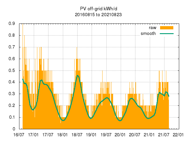
The scheme has been working well all summer. I can swap in the off-grid MagSafe plug when there's been plenty of sun, and swap back when it cuts out or starts to flicker and the adapter/inverter starts to make a slight noise. I'm fairly sure that it's helped me get a fairly steady ~0.3kWh/d from the off-grid system, even though the off-grid battery bank seems to hold very little charge. (For example, it's hit FULL today, but may not be able to keep the router powered off-grid through the night.) Helping me to use excess at the time without worrying about letting out any magic smoke is good!